Mode A (Part 9/12) 🕊️
Paul Tagliamonte 2026-09-08 diyIf you're looking for it, the intro to the PHY (layer 1) that this belongs at a high level and listing of the parts that make it up (including this one) is on the phy post.
While developing Pigeon, I’ve called the group of all the configuration of the Layer 1 PHY parameters the “Mode”. I’ve experimented with a few different “modes”, but one in particular has been the most resilient to the innumerable mistakes and bugs i’ve wrought into existence – and that is the first mode I wrote down, “Mode A”. This is even (mostly) backwards compatible to my original Go implementation of Pigeon Mode A (back in 2022) over the air, and has largely withstood the problems I’ve thrown at it.
I’ve removed the bulk of the support I wrote out for other modes, but i’m likely to bring them back over time as I use pigeon to learn more (such as “Mode B” (QAM-16), “Mode C” (QAM-16 NUC), and “Mode AW” which is the exact same as Mode A, except 5MHz in bandwidth. More to come on those as I get further along – but for now let’s braindump the parameters i’ve picked out for Mode A:
| Attribute | Value | Description |
| Rate | 2.5 MHz | Sampling Rate / Bandwidth |
| LCG | 3149721335 | LCG "RNG" whitening constant (randomly selected) |
| Preamble | seq=16, order=4, count=2 | (this is as-written in the preamble post) |
| Modulation | QPSK/QAM-4 | 2 bits per data subcarrier |
| FFT Size | 64 | |
| Cyc Len | 16 | Cyclic Prefix length (16 IQ samples) |
| Symbols | 168 | Number of OFDM Symbols |
| LDPC Table | 802.3an | (this is as-written in the ldpc post) |
| Raw Bits | 14448 | 1806 bytes (168 symbols, 86 data bits per symbol) |
| LDPC Count | 7 | Number of packed LDPC encoded messages |
| Data Bits | 12061 | 1507 bytes |
The last bit to describe here is the Subcarrier Plan. The plan is ordered “negative first” (meaning the 0th bin in-memory is the most negative frequency domain bin of the fft), and within a Mode A OFDM symbol, there are 64 frequency domain bins (so, just to make it explicit: 64 ‘subcarrier usages’ that make up our Mode A ‘subcarrier plan’).
We’ll follow the same structure and conventions that we went through in the post all about OFDM Symbols – which means, we’ll need to place our guard bins, data bins, and pilot bins. I’ll include a copy-paste-able version of the images to follow at the end.
Guard Bins
First up, let’s place our guard bins. As we’ve already gone over, we’re looking to clear some space right up against the high and low end of the frequency range, so let’s go ahead and do that:
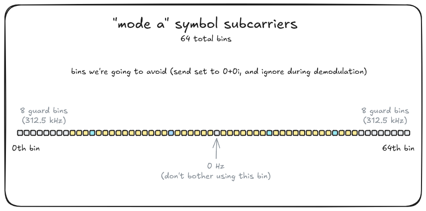
I gave up the center bin (0 Hz) and 8 of the 64 bits on each side (1/4 of the signal!) to give myself a bit of elbow room. This is perhaps definitely a bit overkill, but it’s been an extremely robust choice. If you multiply that through, this accounts for 312.5 kHz of frequency domain “padding” at the high and low end of the bandwidth, or 625.0 kHz of bandwidth which is not to be used.
Pilot Bins
Next up was the pilot bins. We’ve already gone over the purpose (and use) of our pilots, but I’ve found there to be an art to the placement of the pilots. Interpolation between pilot bins has turned out to be very reliable, but extrapolation, on the other hand, has been a major pain, for reasons I don’t fully understand yet.
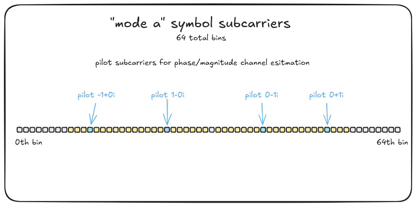
My intent in placement was to pick out roughly even stretches of data bins bracketed between pilots, with as few data subcarriers as practical “outside” of a pilot (using extrapolation). I’ve played a bit with my AGWN simulator(s), as well as logging errors between two SDRs, and the configuration I have this in has been fairly resillant (for whatever reason), and withstood a few rounds of tweaking.
Data Bins
Almost as an afterthought – all of the remaining bins become data bins.
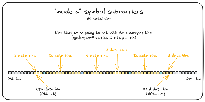
This puts the total number of data bins at 43, which, since Mode A carries data
in QPSK/QAM-4 (two bits per data subcarrier), means we can carry 86 bits of
data per OFDM symbol. That fairly modest capacity is largely due to the
modulation scheme (or fft size, but increasing that has been … fraught) we’re
using for Mode A – but I’ve made up for it by including 168 OFDM symbols
in a single burst in order to have enough data to carry IP traffic without
splitting the packet into two bursts.
With all that designed and on paper, we’re ready to start to tackle the next layer up – our Layer 2, named, creatively, “link”.
Let’s send some link layer data →
The following table is Mode A’s OFDM Subcarrier Plan. This is in negative first ordering (meaning the 0th member is the most negative fft bin, and the Nth is the highest frequency fft bin).
SubcarrierPlan([
  Guard,
  Guard,
  Guard,
  Guard,
  Guard,
  Guard,
  Guard,
  Guard,
  Data,
  Data,
  Data,
  Pilot(iq!(-1.0, 0.0)),
  Data,
  Data,
  Data,
  Data,
  Data,
  Data,
  Data,
  Data,
  Data,
  Data,
  Data,
  Data,
  Pilot(iq!(1.0, 0.0)),
  Data,
  Data,
  Data,
  Data,
  Data,
  Data,
  Guard,
  Data,
  Data,
  Data,
  Data,
  Data,
  Data,
  Data,
  Pilot(iq!(0.0, -1.0)),
  Data,
  Data,
  Data,
  Data,
  Data,
  Data,
  Data,
  Data,
  Data,
  Data,
  Data,
  Data,
  Pilot(iq!(0.0, 1.0)),
  Data,
  Data,
  Data,
  Guard,
  Guard,
  Guard,
  Guard,
  Guard,
  Guard,
  Guard,
  Guard,
])
The following table is Mode A’s frequency-domain preamble. This is, as above, in negative first ordering. I don’t actually think these values matter much (at all)? – but in case they do, here’s what I have. I muck with these a lot and haven’t found many changes in quality of detection or frequency correction yet.
[
  IQ::new(0.0, 0.0),
  IQ::new(0.0, 0.0),
  IQ::polar((TAU / 13.0) * 2.0, 1.0),
  IQ::polar((TAU / 13.0) * 3.0, 1.0),
  IQ::polar((TAU / 13.0) * 4.0, 1.0),
  IQ::polar((TAU / 13.0) * 5.0, 1.0),
  IQ::polar((TAU / 13.0) * 6.0, 1.0),
  IQ::polar((TAU / 13.0) * 7.0, 1.0),
  IQ::polar((TAU / 13.0) * 8.0, 1.0),
  IQ::polar((TAU / 13.0) * 9.0, 1.0),
  IQ::polar((TAU / 13.0) * 10.0, 1.0),
  IQ::polar((TAU / 13.0) * 11.0, 1.0),
  IQ::polar((TAU / 13.0) * 12.0, 1.0),
  IQ::polar((TAU / 13.0) * 13.0, 1.0),
  IQ::new(0.0, 0.0),
  IQ::new(0.0, 0.0),
]