anatomy of our radio sardine tin (Part 3/12) 🕊️
Paul Tagliamonte 2026-09-08 diyIf you're looking for it, the intro to the PHY (layer 1) that this belongs at a high level and listing of the parts that make it up (including this one) is on the phy post.
In the overview, we went over the structure and high level concepts behind a pigeon burst, and in particular, that a burst contains (among other things), a fixed number of “symbols”. This post is all about those symbols, and more specifically, the core parts of “OFDM”.
If you had read the PACKRAT posts, you may remember that we generated a time-domain carrier wave, and modulated it (in the time domain) to encode data. It’s not a huge conceptual step to think about this like a serial data stream, which leads to a question – what if you made it parallel by sending bits on different frequencies at the same time?
Great question! Also, good news! You can, and this works! It’s called FDM, and the only “gotcha” with it is to ensure that there’s enough spacing between signals to avoid your signals from interfering with each other. Each frequency you use in an FDM scheme is usually called a “subcarrier”, and all the subcarriers together are usually called a symbol.
OFDM is a riff on this concept, except frequency spacing is reduced as much as possible, where the signals overlap, but they overlap very carefully, as to not interfere with other signals very close in frequency. Picking these frequencies is otherwise known as satisfying the “zero-isi property” – or, more semantically important to this post – by being “orthogonal” to each other in the frequency domain.
Confused? That’s OK – let’s just cut right to the end of the story - the bins of a frequency domain FFT window are already spaced in a way that satisfies the orthogonality criteria above. Each bin in the frequency domain is, definitionally, already laid out in order to be orthogonal with no further work on our part, and we can treat each bin of an FFT as an OFDM subcarrier, set an amplitude and phase, and when we iFFT that window, it will create a subcarrier in the time domain with the provided amplitude and phase that is orthogonal to all other subcarriers.
This means that we can ignore exactly all of that zero-isi stuff and just read “ofdm” as “use the bins of a frequency domain fft window to encode and decode data”. Not so scary now, is it?
Subcarrier Plan
Great! All done right? Just run some iFFTs and you’re good, right? Well, almost! We need to assign meaning to our frequency-domain bins, and also think through how we encode user data bits to bins.
I refer to the planned use of every symbol’s bin the “Subcarrier Plan”. This is
a mapping of frequency-domain bin to purpose – within pigeon, there are three
“types” of use we assign to subcarriers: guard, data, and pilot.
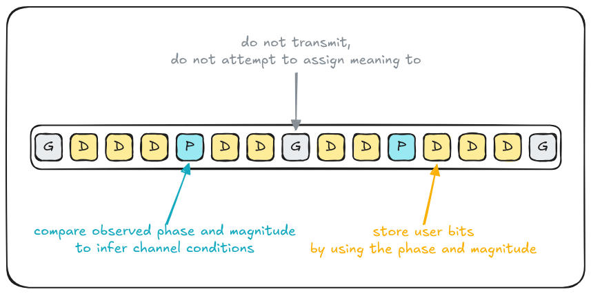
I implemented this with two types, the first of which is the “use” for each
subcarrier contained within a frequency-domain bin. This is called,
imaginatively, the SubcarrierUse. In addition to the purpose, this enum
also contains the well-known value of the Pilot for the plan, which we can
use later for setting the pilot values, or doing channel estimation.
/// Purpose of a single bin (subcarrier) of an OFDM Symbol.
enum SubcarrierUse {
    /// This Subcarrier is encoded by some Modulation
    /// to encode bits of data into.
    Data,

    /// This Subcarrier is used to correct phase
    /// discrepancies or frequency-specific fading.
    ///
    /// The inner `IQ` value is the value of the
    /// pilot subcarrier -- something like
    /// `1+0j`.
    Pilot(IQ),

    /// This Subcarrier is unused, in order to
    /// to avoid interference.
    Guard,
}
Next, the second type I wrote out is the “plan” for how we’re going to use
every single OFDM symbol subcarrier, again, creatively called the
“SubcarrierPlan”. The SubcarrierPlan is a wrapper around a vector of
SubcarrierUses, one for each frequency-domain bin (this will always match the
fft size; and is always in
“negative first”
order).
/// Purpose of every OFDM Symbol's Subcarrier.
struct SubcarrierPlan(Vec<SubcarrierUse>);
Now that we can name and assign a purpose to every subcarrier of an OFDM symbol, it’s high time we got into what each of those purposes actually mean when we construct and decode an OFDM symbol.
Guard Subcarrier
A guard subcarrier is intentionally set to 0+0j when generating a Symbol, and
ignored when receiving one, in order to provide padding in the frequency
domain. There are a long stretch of guard bands on pigeon OFDM symbols at the
highest and lowest frequency bins, which helps with reliability during
reception, restricts the emission bandwidth, helps account for the SDR
front-end passband filtering out signals at the edge of the sampled bandwidth,
and subtle differences in center frequency. Additionally, within most OFDM
systems, the 0Hz center bin is set to function as a guard subcarrier, since
attempting to transmit meaningful information in the 0Hz bin is hard and
especially prone to corruption by the transmitting and receiving SDR (due
to “DC bias”). It’s not worth
fighting with that.
Pilot Subcarrier
A pilot subcarrier are bins set to a known amplitude and phase in order to correct for changes in phase and amplitude over the symbol’s frequency range. The channel conditions may cause more attenuation in part of the bandwidth than others, or residual uncorrected (or continuously changing) phase or frequency offsets.
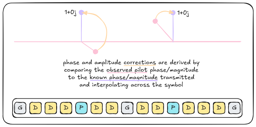
Since pilot subcarriers are in predefined locations in the symbol, with a predefined phase and amplitude, the channel can be estimated for a given symbol, and interpolated across the bandwidth to account for amplitude and phase errors across all subcarriers.
Data Subcarrier
A data subcarrier is modulated to encode bits of data to be recovered by the receiver according to the configured modulation scheme. The phase and amplitude of the subcarrier will be encoded according to the specific modulation scheme for the data subcarriers.
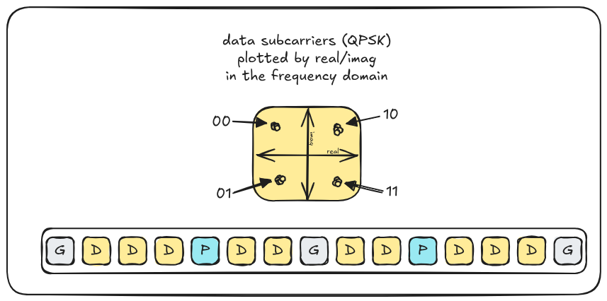
Since a Pigeon Burst contains a fixed number of symbols, I have been careful to pick a symbol count to leave me at least 1300 bytes for the data link to carry IPv6. By using a modulation scheme that allows for more bits to be sent on a single subcarrier, the number of symbols can be decreased, and conversely, the fewer bits, the greater the number of symbols.
In general, the more bits that are being sent on a single subcarrier, the more the tolerance for errors decreases, which adds complexity in the form of error correction due to flipped bits. As the number of bits are reduced, the amount of phase and amplitude error tolerance increases. Since my channel estimation code is exceptionally crude, I’ve opted for low bit cardinality schemes.
Creating a Burst
Beyond our SubcarrierPlan and SubcarrierUse, we also need a place to store
the data we’re generating, or reading in off the air. I have two main types
for this – the first is a Symbol, which is made up of frequency domain
bins, which have been transformed via an fft from the receiver, or will be
transformed via an ifft to generate our output signal. Each symbol is
exactly the fft size long.
/// Negative-first frequency domain subcarriers.
struct Symbol(Vec<IQ>);
Now, we can tie the plan and set of symbols together in what we’ve termed a
“Burst” in this series – a collection of Symbols which contain data
encoded within. This is a “higher level” construct than the topic of this post
(what is a “symbol”) but the line is a bit blurred here since the
SubcarrierPlan is per-burst not per-symbol, so we’ll include the whole thing
for completeness sake.
struct Burst {
    /// Planned use for the Subcarriers contained within
    /// the Symbol.
    plan: SubcarrierPlan,

    /// Each OFDM Symbol, in order.
    symbols: Vec<Symbol>,
}
This means that, for each Symbol, zippping the IQ bins with the
SubcarrierPlan will give you the SubcarrierUse for that bin – which
allows for populating things like the Data subcarriers with
modulated IQ samples, or setting the Pilot
to the planned IQ value.
Here’s a lightly-edited (for clarity, apologies for the lack of rustfmt which is particularlly bad here – dealing with h-scrolling issues) version of how bits get multiplexed into subcarriers within pigeon:
impl Burst {

  ..

  /// Read bits of data in, and multiplex that into a
  /// frequency-domain OFDM burst.
  pub fn multiplex(
    &self,
    dst: &mut Burst,
    src: &bit::Vector
  ) {
    // pre-allocate all our data subcarriers.
    let plan = self.plan;
    let mut raw_dst = vec![
      iq!(0.0, 0.0);
      plan.data_subcarriers()
    ];

    let bits = plan.data_subcarriers()
      * Qam::<4>::BITS_PER_SYMBOL;

    // for each OFDM symbol, we're going to populate
    // all of those symbol's subcarriers.

    for symbol in 0..self.config.symbols {
      let bits_start = bits * symbol;
      let bits_end = bits_start + bits;
      let symbol = &mut dst.symbols[symbol];

      // fill all the bins with 0+0j, which will
      // ensure guard bins (which we won't
      // explicitly set below) are set to 0.
      symbol.bins.fill(IQ::new(0.0, 0.0));

      // slice `src` to only view the bits within this
      // ofdm symbol.
      let src = src.slice(bits_start, bits_end);

      // modulate the ofdm bits into our slice
      // of data subcarriers (`raw_dst`).
      let n = Qam::<4>::modulate(
        &mut raw_dst,
        &src
      );

      // copy `raw_dst`'s data subcarriers to
      // each ofdm symbol's data subcarriers.
      for (dst, src) in symbol
         .iter_data_mut(&plan)
         .zip(&raw_dst)
      {
          *dst = *src;
      }

      // copy the well-known pilots into the symbol
      // in the right locations.
      for (planned_pilot, pilot) in symbol
         .iter_pilot_mut(&plan)
      {
        *pilot = *planned_pilot;
      }
    }
  }
}
Once these are all set, we can think about constructing a time-domain OFDM signal for each burst. However, before we do that, we need to add a “Cyclic Prefix”. What is a Cyclic Prefix? Glad you asked!
Cyclic Prefix
When the OFDM signal is transmitted, that signal will travel through freespace between the two antenans, but also bounce or bend through less direct paths, which increases the distance between the transmitter and receiver. This has the practical effect of overlaying the signal multiple times – like having a very fast conversation in a very echoey room. This is called “intersymbol interference”, or commonly, “ISI”.
To mitigate this, OFDM protocols generally use a “Cyclic Prefix” a technique where, in the time domain, the last N IQ samples from the symbol are copied to be transmitted before the Symbol actually begins. This has the practical effect of allowing the cyclic prefix – the transition between two full size symbols – to be subject to the worst of the interference, as well as allowing small timing mistakes to still appear to be, over the average of the slightly misaligned symbol window, mostly correct.
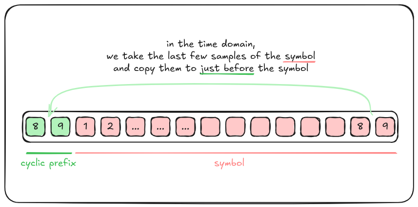
Additionally, this also has the effect of mirroring the properties of the preamble, such that the Cyclic Prefix can also be used by the fine frequency offset estimation code to gain additional resolution on frequency offsets, as well as attempt to characterize changes in frequency over the duration of the Burst.
Going from IQ to a Burst and back again
Now that we can take bits and put them into a frequency-domain Burst
struct, as well as know how to construct the Cyclic Prefix, we can give
implementing this a shot. Let’s start off with the hard one – taking
a frequency-domain (already modulated) pigeon Burst (a bunch of OFDM Symbols)
and turn that into IQ using an ifft with a cyclic prefix:
impl Burst {
  pub fn encode(
      &self,
      dst: &mut [IQ],
      src: &Burst,
  ) -> Result<(), Error> {
    // size (in iq samples) of the time-domain symbol
    // and cyclic prefix.
    let symbol_len = self.config.subcarriers +
      self.config.cyclic_prefix_length;

    // used for fft operations.
    let mut bins = vec![IQ::default(); self.config.subcarriers];

    for symbol in 0..self.config.symbols {

      // slice out our symbol's time-domain iq range
      let start = symbol * symbol_len;
      let end = start + symbol_len;
      let dst = &mut dst[start..end];

      // copy the frequency-domain (qam modulated) data
      // to our working buffer here
      bins.copy_from_slice(&src.symbols[symbol].bins);

      // shift from negative-first order to zero-first
      // ordering here however you do it.
      shift_neg_to_zero(&mut bins);

      // do an ifft to take the frequency domain data
      // and produce a time-domain iq stream into
      // our output window
      ifft(
        &mut dst[self.config.cyclic_prefix_length..],
        &bins,
      )?;

      // now, copy the last few samples to the beginning of the
      // time-domain signal (cyclic prefix)

      let (cyclic_prefix, symbol) = dst.split_at_mut(
        self.config.cyclic_prefix_length
      );

      let last_n = symbol.len() -
        self.config.cyclic_prefix_length;

      cyclic_prefix.copy_from_slice(&symbol[last_n..]);
    }

    Ok(())
  }
}
The other way around turns out to be a bit easier – we don’t have to
construct very much, we only really need to do a fft to transform
our IQ from the time-domain into the frequency-domain, and write that data
out into the right spot in the Burst. Let’s sketch that out:
impl Burst {
  pub fn decode(
    &mut self,
    dst: &mut Burst,
    src: &[IQ],
  ) -> Result<(), Error> {
    let symbol_len = self.config.subcarriers +
      self.config.cyclic_prefix_length;

    for symbol in 0..self.config.symbols {

      // slice out our symbol's time-domain iq range
      let start = symbol * symbol_len;
      let end = start + symbol_len;
      let src = &src[start..end];

      // pull off the cyclic prefix of the symbol
      let (_cyclic_prefix, src) = src.split_at(
        self.config.cyclic_prefix_length);

      let bins = &mut dst.symbols[symbol].bins;

      // transform the iq samples into the frequency
      // domain
      fft(bins, Some(src))?;
      shift_zero_to_neg(bins);
    }

    Ok(())
  }
}
In an ideal world, this would have been it, we can bring out the cake and move along with our day. We now have what we need to convert from user-provided bits to transmit into IQ samples (and, at a very base level, back again!). The only trouble is – where do these bursts start and stop? How do we correct for noise and distortion? Turns out life is not ideal, and the remaining work on the PHY is to deal with the reality of sending and receiving data over the air.